
MLAstro SHG700 Spectroscope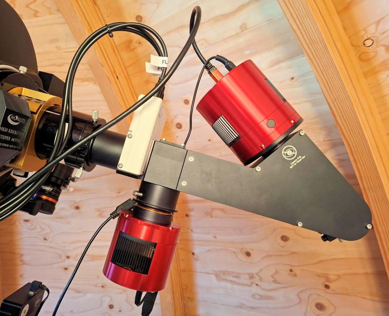 Figure 1: The MLAstro SHG700 spectroscope behind the C11 EdgeHD. [This page is still under construction (last update 12 April 2026) and will be updated regularly in the coming months (up to about June 2026), so please come back again for the latest developments.] In 2023 I had the chance to borrow a Shelyak LHires III from a university for half a year. After I returned it I considered getting one myself. Christian Buil's 3D Sol'Ex/Star'Ex had attracted my attention as well, but I feared the plastics in it, wondered how that would affect stability. My initial plan was to make an aluminium version of the Star'Ex, but then news reached me about 'this guy from Vietnam' who had designed an aluminium version. This guy is Minh T. Nguyen, who had started MLAstro, and produced these magnificent Spectroheliographs. I wanted to use a spectroscope for Pro-Am work through the AAVSO, to get spectra from comets, and perhaps do some fun stuff as measuring the rotation speed of the Sun, Jupiter, and perhaps the orbital speeds of the Jovian Moons. A spectroheliograph, however, is a spectroscope meant to be used for imaging the Sun in selectable wavelengths, but being closely designed after the Sol'Ex/Star'Ex, it can be converted to a spectroscope for deep-sky spectroscopy. 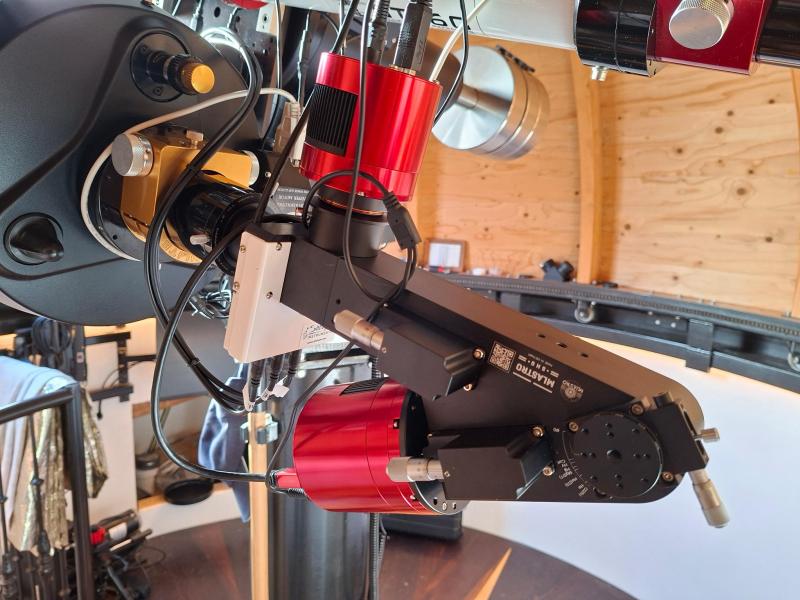 Figure 2: The MLAstro SHG700 spectroscope at the side of the micrometers. The SHG700 has several major advantages over the Sol'Ex and Star'Ex:
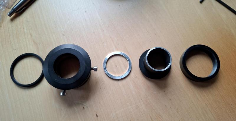
The SHG700 I received came from batch 6 and arrived in October 2025. It is used with a 20µ slit behind the Celestron C11 XLT EdgeHD with a ZWO ASI2600MM Pro as science camera and a ZWO ASI1600MM Pro Cool as guide camera. Using the SHG700 as deep-sky spectroscope In order to adapt the SHG700 to deep-sky spectroscopy a sturdy focuser, calibration unit, guide unit, another slit, and a control box are required. Focuser requirement Figure 3: The new Moonlite focuser for the MLAstro SHG700. During initial testing it soon became apparent that the spectroscope was a bit too heavy for the Moonlite focuser that I had in use at the time. This version was the model with eight small 10mm diameter bearings (see figure 1 and figure 2). The spectroscope with calibration module and the two ZWO cameras weighs about 3kg. Although the focuser had no issue with holding and moving the weight in focus direction, with the centre of gravity at approximately 30cm from the focuser, the lateral force the spectroscope produced was too much for the small bearings the focuser was equipped with, causing regular failure of them (the outer shell broke in two). The focuser was therefore replaced by the four-bearing MoonLite Revised CHL 2.5 inch Large Format Crayford EDGE version which has no issue lifting the spectroscope, nor with the lateral force (see figure 3). In addition flexure reduced significantly thanks to the sturdier design. Calibration module and ASCOM control box Figure 4: The 12V four channel relais board for controlling the Alpy calibration module in home-made housing. I added a Shelyak Alpy 600 calibration module to it (the white flat box in figure 1). This module has a NeAr (Neon-Argon) calibration lamp, a tungsten lamp for creating flats, and it can block incoming light from the telescope so that darks can be taken. The module fits the SHG700 well, it only requires four M4 x 60mm Allen bolts (these are not included in the module, nor in the SHG700). Controlling the calibration module from data-acquisition software (CCDciel in this case) can be done using a switch like the SOS Electronics 12V four channel relais board (see figure 4) in combination with NOYTIO USB Relay Controller ASCOM Switch Driver. There is no need for soldering or electronics knowledge to use this board, but for convenience I added LEDs to indicate which switch is enabled, and two 1A diodes: one between switch four and three and one between four and two. In this way switch four is used to enable darks-mode (which normally is enabled by switch two and three simultaneously). Using a non-mini camera for guidingMLAstro already offered an aluminium guiding module, so that was ordered together with the SHG700. Like the spectroscope itself it is very well made, but it is meant to work with a mini camera like the ZWO ASI120MM Mini. That mini-camera should be mounted in a ZWO Helical focuser (not included) attached to the guide-module. For deeps-sky spectroscopy this can cause two issues: The helical focuser may not be stable enough to ensure a fixed position of the slit on the guide camera chip during long sessions (during which the orientation of the spectroscope changes), and cameras with larger chips will not get the right back-focus distance when using the helical focuser as that focuser is too long. 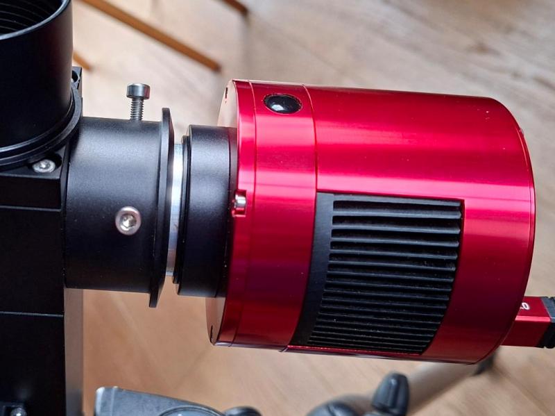 Figure 5: The low-profile adapter that holds the guide-camera to the guiding module of the MLAstro SHG700. As guiding camera I decided to use an old ZWO ASI1600MM Pro Cool that I once exposed to direct sunlight, which caused a permanent ghost image of the Sun on the chip, rendering it less suitable for deep-sky imaging. The advantage of this camera is that it has a large imaging chip, which is beneficial to plate-solving. It sees the sky through the reflective surface of the spectroscope's entrance slit. I thus created another solution: instead of the helical focuser I mounted a low-profile 2" to 1.25" adapter on the SHG700 (for parts see figure 13). The camera is equipped with a standard 1.25" nose-cone that fits the low-profile adapter. Downsides of this solution are twofold as well: the adapter only has a single clamp-screw as a result of which the camera could wobble some 6 pixels, way too much to be useful. By adding a second screw this issue was completely overcome and the slit now remains stable well within a pixel. The other issue is that this solution is not a focuser, but by using spacers of varying thickness (one home-made 1.25" x 2.5mm aluminium spacer and a set of Baader T2 0.3, 0.5, and 1.0mm spacers) this was also overcome. Fitting a wider slit Figure 6: The home-made aluminum slit holder for the Shelyak Gen2 14-20-26-32 µm slit. Originally the SHG700 is equipped with a 7µ wide reflective entrance slit. For solar imaging this is fine, even better: the narrower the better as one would only need one column of pixels to scan the full solar disk. For deep-sky spectroscopy, however, we want to properly sample the incoming spectrum. As science camera I had chosen the ZWO ASI2600MM Pro, a camera with a APS-C size chip and 3.76µ pixels. As the SHG700 has the same optics on both sides of the reflective grating, the slit is projected as wide on the imaging chip as it actually is. Being 7µ wide, the image of it would be just under 2 pixels, too low to satisfy the Nyquist criterion. I had thus ordered a Gen2 14-20-26-32 µm slit (with 25 µm central hole) from Shelyak. This slit was meant for the Star'Ex and a 3D-print slit holder is available. Sadly enough these 3D designs do not fit the SHG700, but then I am not a fan of plastics anyway. So I had one printed as example, created a drawing for an aluminium version, and machined that in my workshop (see figure 6). Meanwhile Minh is working on an aluminium slit holder for this slit as well, so hopefully he can deliver these soon. Guide camera back-focus Figure 7: MLAstro SHG700 back-focus distance behind a field flattener like in a Celestron C11 EdgeHD. The first time I started the guide-camera was quite disappointing as the stars were terribly elongated, making plate-solving impossible. The slit of the SHG700 was approximately 30mm too far behind the official back-focus distance of the Celestron C11 XLT EdgeHD of 146.05mm. So I removed the Shelyak calibration unit to see if that would improve the image quality, but it made things worse. On itself this was not much of a surprise as the stars were elongated in a radial direction, indicating that the camera was too close to the built-in flattener. I then realised that the guiding module has a double lens-group as well and that the focal length of that whole lens-group (the sum of the two purple lines in figure 7) determined the proper location of the slit. From Minh I learned that this focal length is approximately 100mm, so I remounted the calibration module, added a 40mm long T2-spacer to the SHG700 and brought the slit at approximately 90-100mm from the official back-focus plane (so a bit short, but wanted to check if the image indeed improved). Using the SCT's native focuser focus was restored and near to round round stars appeared! Guide-camera plate-solving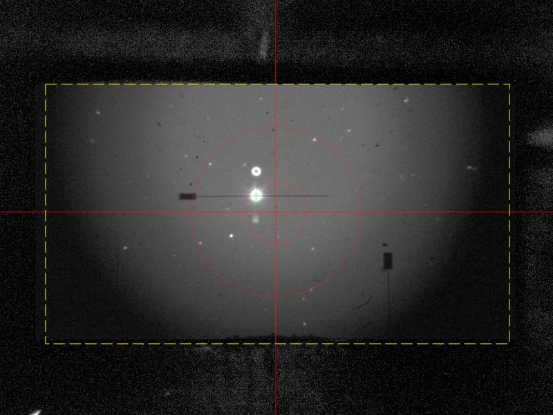 Figure 8: The full FOV of the ASI1600MM Pro Cool guide camera of the SHG700 and the plate-solve crop-line. Despite the stars being more or less round now the image would still not plate-solve, especially when a bright star was within the field of view (FOV). In figure 8 the full FOV of the ASI1600MM Pro Cool guide camera is shown with Rho Cas at the slit of the SHG700. Vertically above and below it double and triple reflections of Rho Cas can be seen (the one above looks like a doughnut), which are caused by the internal reflections in the glass substrate of the slit. On itself not a problem as this is only the guide-image, but plate-solve software like ASTAP fails as it sees the reflections as real stars and thus generates quads connecting to them. The author of ASTAP, Han Kleijn, kindly informed me that PlateSolve3 had no issue with these additional reflections, but that it required the image to be cropped to the actual area that could show stars as indicated with a yellow dashed line in figure 8. The area outside the dashed line only shows the slit-holder and other internal parts of the guiding module, confusing PlateSolve3 with empty (i.e. star-less) space. Patrick Chevalley, the author of the imaging software CCDciel, kindly implemented a guide-camera crop-option in his software, and now plate-solving works well, but only on nights with good transparency and enough stars in the FOV. In order to make it work even better those reflections have to be eliminated. Getting rid of double slit reflections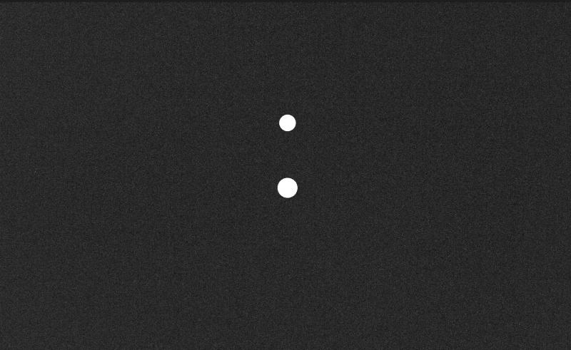 Figure 9: Guider dark-mask file to remove double reflections from a spectroscope slit. The easiest way to get rid of the slit reflections is using a mask in the dark-frame of the guider (and finder) camera (see figure 9), in combination with a purposely ill-aligned telescope. The latter sounds odd, but if the misalignment of the scope is more than half the FOV, the bright target will not be within it during the initial plate-solve. CCDciel does a double slew and plate-solve to get the target on the slit. The idea is to let the first slew point the scope close to the target, and the second slew to get the target on the slit. The double reflections may cause the plate-solve to fail, but the target and its reflections will be at a predictable location thanks to the first proximity slew (how well the second slew goes depends on the quality of the mount). With this approach the reflections are at a predictable location after the second slew and the mask will ensure they are removed (see figure 10). Creating this dark-mask frame can be done as follows: In CCDciel: - create a dark-frame from the guider camera. - take an image of the guide-scope with a bright star at the final slit position. 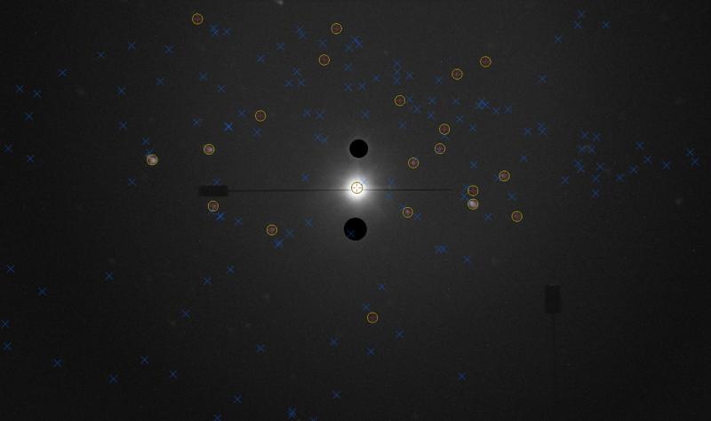 Figure 10: The resulting guider-image of the spectroscope slit during plate-solving. In Siril: - open both FITS files and save them as TIFF. In PaintShop Pro or PhotoShop: - open the guider TIFF image. - add an adjustment layer and set it to 'Curves'. - adjust the curve (stretch the image) to make the reflections visible. - add the dark-frame as a new layer and make it invisible. - add a new raster layer 'star-mask'. - create two white circles in the 'star-mask' layer at the location of the reflections, make them slightly larger than the reflections. - make the dark-frame layer visible (this will give figure 9). - save the merged image as dark-mask.tiff (as monochrome or colour, depending on the guide camera, and with the same bit depth). In Siril: - open dark-mask.tiff. - save it as dark-mask.FITS with the same bit-depth as the guide-camera. In ASTAP (only required when the guide-camera is binning): - open dark-mask.FITS. - add the following two rows to the header (in my case the 2 x 2 binning is used):
- Save the FITS header. In CCDciel: - in the Finder Camera section, click on the Dark-button and choose Load dark file. - load the dark-mask.TIFF. - test the dark-mask file by clicking on Start Preview Loop button (and enable Save preview images). - if the mask appears try a precision slew with plate-solving (this will give figure 10). First light with various gratings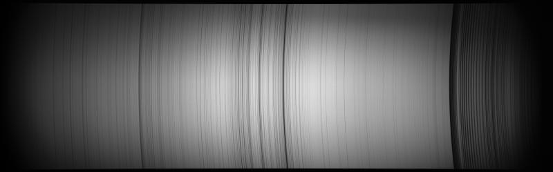 Figure 11: First-light spectrum of daylight sky with the SHG700 (2400l/mm, 7µ slit) and ZWO ASI2600MM Pro. First light was done on a tripod by simply aiming the SHG700 to the sky at daytime. Despite it large sensor, but thanks to the excellent optics in the SHG700, the spectrum is razor sharp all over the field of view (see figure 11, click here for the full version in jpg-format and here as tiff)! This was way better than I hoped fore and it turned out to produce a 100nm wide spectrum when using a 2400l/mm grating in combination with the ZWO ASI2600MM Pro. Combined with the 20µ slit a resolving power of around R=15000 can be achieved at the H-alpha wavelength (see figure 16). 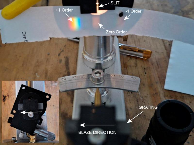 Figure 12: The zero, +1 and -1 orders of a 300l/mm grating. The inset shows the grating as set-up in this test. I had also ordered a 300l/mm grating from MLAstro for full visible light observations, but that delivered a 1000nm wide field of view in this set-up (see figure 14), a bit too much of the good thing. So from Thorlabs I ordered a 600l/mm ruled grating (blazed @ 500nm) and as expected it delivers a 500nm wide spectrum (see figure 15), good for wide spectra of comets, etc. The ruled grating has the advantage over holographic ones that it has higher efficiency, quite useful in faint comet observations. MLAstro does sell gratings of this density, but ordering through Thorlabs was quicker this time. In April 2026 the first two spectra were submitted to the AAVSO. Both were of 32 Cyg, one with the 600lpmm grating and one with 2400lpmm grating, both of which were reviewed and accepted. Blaze direction When using a lower density blazed grating, attention should be paid to the mounting direction of it with respect to the grating holder. For best performance (i.e. highest efficiency/reflectivity) the blaze arrow should be pointing against the incoming light beam. The correct orientation of the grating is shown in figure 12. For a 2400l/mm grating the difference in intensity between the +1 and -1 orders is only 4.5%, but for a 300l/mm grating this is approximately 85% (the difference between these two order is clearly visible in figure 12)! If you have any questions and/or remarks please let me know. |
InFINNity Deck... Astrophotography... Astro-Software... Astro Reach-out... Equipment... White papers...
Telescopes... SHG700 Spectroscope 10Micron GM3000HPS Test tools... Sundials...