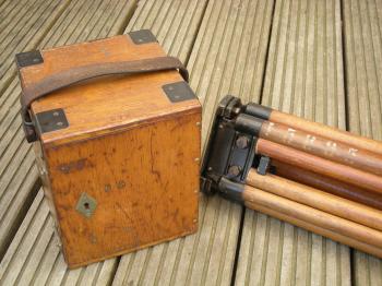
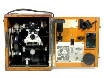
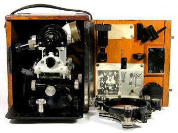
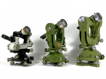
1924 Carl Zeiss Th1 TheodoliteWhile discussing the repair of my Wild TC1 at the workshop of a Leica dealer here in the Netherlands in May 2011, we came to discuss early theodolites like the Wild T2 and Wild T3 in my collection. Soon the discussion went to another optical theodolite, once designed by Heinrich Wild during his years as manager of the Geo department of Carl Zeiss, patented by him in 1921 and first produced by Zeiss in 1924.1,2,12 This instrument, the Zeiss Th1, was the first theodolite to be equipped with glass circles and a plan parallel coincidence reading mechanism.3 The whole system fully relied on glass components such as prisms and lenses, hence the name optical theodolite, and marked the dawn of a new era in theodolite design.2,4 Not only was it possible to create smaller instruments without loss of precision, it also meant that higher accuracies could be achieved thanks to diametrical reading of the circles (i.e. the readings at two opposite sides of the circle are automatically averaged by sighting them simultaneously). Having the telescope that reads the circle at the same side as the main telescope's ocular meant that the surveyor could hold his stance, which allowed measurements on smaller platforms and by a single observer.5 The design was that successful that most theodolites designed after the Th1 came into production, like the Wild Heerbrugg theodolites (starting with the Wild T2), the Tavistock theodolite by Cooke, Troughton & Simms, and the Tavistock theodolite by Watts-Zeiss, were designed along the same lines.2 Design features When Heinrich Wild designed the Th1 it was intended to meet the following requirements:2
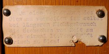
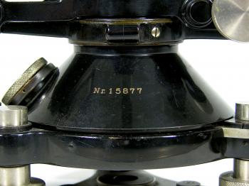
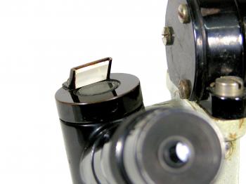
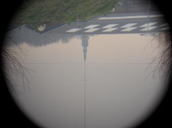
Provenance7Checking the largest auction site on the internet lead to Robert Greenebaum in the US, who had one for sale. The instrument belonged to his late father Ira Greenebaum (NYC, 15 March 1922 NYC - Boston, 3 June 2003, see figure 5) who joined the US Army Corps of Engineers as surveyor in the early 1940s. As a sergeant he was stationed at various times in England, France and Belgium. In Belgium he participated in the battle of the Bulge (Dutch: Ardennenoffensief). At one point while being in the 3rd Army under general Patton he was sent to assess the flood stage of a river, possibly the Marne, and gave his report directly to Patton. It was somewhere during his time in Europe that he picked up the instrument and eventually took it home.  Figure 4: Ira on the job for TVA, in front of him a levelling staff and tripod (collection R. Greenebaum) Prior to his time in the army, in the 1930s, he worked for the Tennessee Valley Authority in the south central US as a surveyor for the hydroelectric development project. Later in life he worked in the construction industry in the New York metro area as a job superintendent and later as an estimator and insurance investigator. Back in the US Ira mainly used the instrument as a telescope to have a look at the heavens together with his children. Finally Robert decided to part with the instrument and thanks to the internet it came into my collection. AccuracyThe Th1 was the first theodolite to feature glass circles (75mm diameter horizontal and 50mm diameter vertical) and an optical reading system.8 The Th1 does not have a compensator for the vertical index, a large coincidence vial with a settling accuracy of 0.7" is used instead.9 The Th1 has sexagesimal circles divided in degrees down to 20 arc minutes intervals (centesimal ThI's have been made as well and were divided in 0.2 gon intervals) and can be read using a micrometer down to 1" (or 1 mgon for centesimal instruments) and estimated to about 0.1" (or 0.1 mgon for centesimal instruments).9,10 The accuracy of the direction reading is given as 1.3".9 Reading the circles is done using a separate microscope that can be swung around to facilitate reading of the circles after transit (see figure 4). The circles and micrometer are illuminated using prisms and white reflectors (see figures 20, 21 and 22). Later theodolites would have larger and coated optical systems and glass mirrors instead of white reflectors to achieve better visibility of the circles. Tests performed by W. Schermerhorn using prof Hk.J. Heuvelink's method of circle testing in Delft, the Netherlands, in 1924 showed the instrument was accurate down to 1.08 arc seconds on average for the whole circle, while 2 arc seconds was given for a single reading (making it no point estimating the micrometer to decimals).10 The telescope has a magnification of 18 times and gives an inverted view (see figure 25). The manufacturer stated in their manual that "...errors of collimation in azimuth and altitude may be eliminated by taking readings in both positions of the telescope..." and that the telescope was constructed that well in the workshop that "... no means of adjustment are provided to enable the observer himself to rectify the stadia plate..." and that the "... horizontal axis is likewise not adjustable.".11 Subsequently directions are given to adjust the vertical vial and even how to clean the primary axis (which "...should preferably be entrusted to an instrument maker..."), but none to adjust any horizontal collimation. Tests performed with the Th1 in my collection revealed a horizontal collimation error of about 41 arc seconds (so 1'22" difference in two opposite readings). The vertical collimation can be adjusted, something I had to do after I had taken the axis completely apart for maintenance. After careful adjustment - where I thought I had adjusted it within 10 arc seconds - the index error was tested next day, still showing a 36 arc seconds index error on average. The standard deviation in vertical measurement (after correction for the index error) was 8 arc seconds over eight observations. The instrumentAlthough the instrument was patented in 1921 production did not start at Carl Zeiss Jena before 1924.12 That year the Th1 would have cost GM1025,- (GM = Goldmark), quite a bit more that their RThII, which was sold at GM640,-.13 Zeiss continued the Th1 until 1930, in which period some 1000 instruments were made, 250 more than the total production of RThII's.12 Compared to about 7,000 T3's and 40,000 T2's produced by Wild Heerbrugg in a 45 year period this is a very limited number of instruments. The serial number on the instrument indicates that this particular one was produced in the starting year 1924.12 The box and instrument would originally have the same serial,12 while in this case the box has serial (15)878 and the instrument is numbered 15877. This means that the original owner at least had two of these instruments which got interchanged between the boxes. With the tripod marked 15885 it is quite likely that a third Zeiss Th1 was in the original inventory and perhaps even all the numbers in between. The instrument tested by Schermerhorn (see above under Accuracy) was received in May 1924 and had instrument number 15897,10 and as most known surviving ThI's have serials above 16000,14 this instrument is an exceptional early and rare example. Several design features, like the white reflectors, the way the light passes through the circles and the clamping mechanism of the tribrach, were clearly not yet fully developed and greatly improved when Heinrich Wild created his T2 and forthcoming instruments for his own company Wild Heerbrugg. From here one these improved features became standard and remained virtually unchanged until the advent of total stations like the Wild TC1 in the 1980s. In 1924 J.M.H. Heines wrote an article in the Dutch magazine Tijdschrift voor Kadaster en Landmeetkunde on the Th1 and its successor the Wild T2. He concluded that both instruments not only got the attention but also the admiration of the author and that it would be justified if they would obtain a solid position in the field of surveying.15 The latter certainly was the case for the Wild T2, but sadly enough not for the Th1. Notes:[2]: E.R.L. Peake, 'The Tavistock Theodolite: A paper read at the Afternoon Meeting of the Society on 11 February 1929', in: The Geographical Journal, Vol. 73, No. 6 (Jun., 1929), (1929), pp.513-519. [3]: F. Deumlich, Instrumentenkunde der Vermessungstechnik, (Berlin, 1972), p.15. [4]: D.A. Wallis, 'History of Angle Measurement', in: International Federation of Surveyors, FIG, (2005), p.12. [6]: Circular vials were already in use before that time, mainly to roughly set levelling instruments, rather than theodolites, although the 1911 RTh II was equipped with one as well. So far I have not seen earlier examples of detachable tribrachs. For circular vials and their early application on instruments, see M. de Vos, Leerboek der Lagere Geodesie ... met 196 figuren in den tekst., (Groningen, 1905), pp. 26, 145. [7]: from telephonic and e-mail correspondence with Robert Greenebaum. [8]: Carl Zeiss - Jena, 'Zeiss Theodolite - Theodolit I mit selbststättiger Mittelbildung, gemeinsamer Ablesung und optischem Mikrometer', in: Carl Zeiss - Jena, Leaflet: Geo 60, (1926), pp.5. [9]: Carl Zeiss - Jena, 'Theodolite, Model No. I with automatic reading mean reading, conjoint reading, and optical micrometer.', in: Carl Zeiss - Jena, Leaflet: Geo 33, (1924). [10]: W. Schermerhorn, 'Vergleichung des neuen Zeiss-Theodolites mit heutigen Konstruktionen', in: Zeitschrift für Instrumentenkunde, XLV Jahrgang, Januar 1925, (1925), pp.16-35. [11]: Carl Zeiss - Jena, 'Directions for the Use of Theodolite Model No.', in: Carl Zeiss - Jena, Leaflet: Geo 34, (1924). [13]: Carl Zeiss Jena, Druckschrift Geo54a, 1926. With many thanks to Dr. Wolfgang Wimmer and Ms. Marte Schwabe of the Zeiss Archives for sending me a digital copy. If you have any questions and/or remarks please let me know. |
Surveyor's crosses... Geodetic Sextants... Theodolites... Total Stations... Levels... Standards... Tools... Firms...
19th c. SDL 1919 K&E 1926 Zeiss RThII 1924 Zeiss Th1 1929 Wild T2 1937 Wild T3 (astronomic) 1939 Wild T3 (geodetic) 1943 CT&S Tavistock 1948 Wild T1 1950s Askania Tu400 1952 Wild RDH 1956 Wild T0 1960s Zeiss BRT 006 1961 Wild T1A 1961 Wild MIL-ABLE T2 1962 Wild T2 1963 Wild RDS 1966 Kern DKM2 1969 Wild T2E 1969 Wild Di10 / 1972 T2 1976 Wild Di3S / 1963 T2 1976/79 Wild T2 mod - DI4 1990 Wild T2 mod - Di1000


