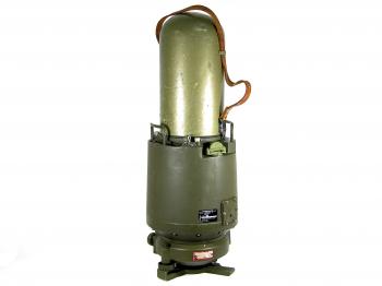
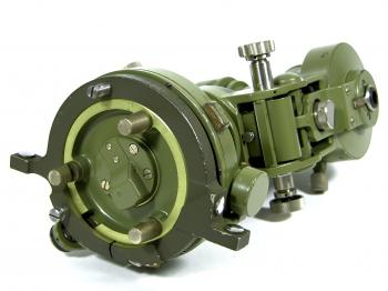
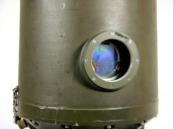
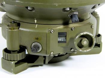
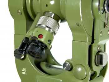
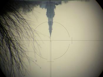
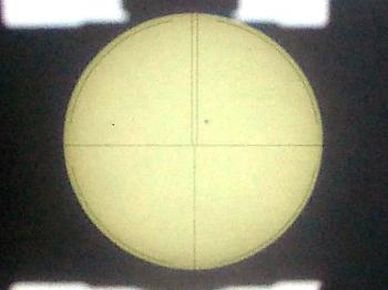
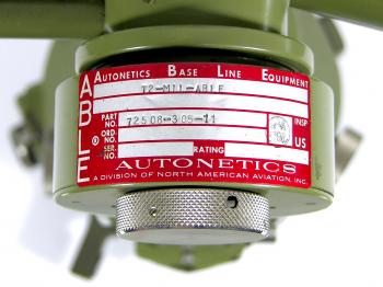
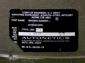
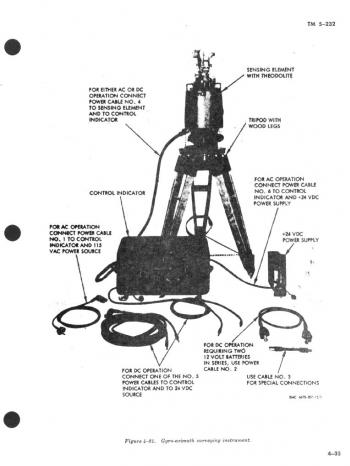
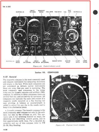
1961 Wild Heerbrugg MIL-ABLE Gyro T2This exceptional piece of equipment was donated to my collection by a befriended collector in 2010. It concerns a military version of a Wild Heerbugg T2 (model T2-56-C-MIL) combined with an "Azimuth-Gyro, Artillery Model C2B ABLE". The abbreviation ABLE stands for Autonetics Base Line Equipment, but in general the combination was either referred to as "ABLE Orienter"1 or "Gyro-Azimuth Surveying Instrument"2. According to the U.S. army field manual FM 6-2 the "... artillery gyro azimuth surveying instrument (fig. 136) (azimuth gyro) is a portable gyrocompass used to determine a true direction. With this instrument, a direction can be determined under conditions of poor visibility without lengthy computations and with an accuracy that is comparable to that of astronomic observations. Direction is determined by observing the effect of the rotation of the earth on the gyroscope and applying appropriate corrections to the instrument. This instrument is for use in latitudes between 60° north and 60° south of the equator." The instrument was "...authorized for field artillery howitzer, gun, and missile battalions; for the survey element in the headquarters battery of division artillery; and for the batteries of the target acquisition battalion."3 Originally the set would comprise of a Sensing Element (the gyro), a 0.002-mil T2 (the Wild T2 theodolite) and a Control Indicator, which was "...an electronic package which provides power to the gyro rotor, the heating elements, and the signals for measuring the amount and direction of the gyro misalinement [sic]. The control indicator panel [...] provides the controls and indicators necessary for the operation and the directional alinement [sic] of the instrument.3 The Wild T2 on top is not an ordinary one, but modified at several points for military use:
Accuracy The MIL-ABLE Wild T2 is as accurate as any period Wild T2, although it has now to be expressed in mills. Both circles can be read down to 0.002 mils and estimated to 0.001 mils. The quality of the azimuth provided by the gyro depended on the latitude and the number of observations. The field manual contains a table that provides a guideline for the number of observations that should be taken to achieve a certain accuracy at a certain latitude (see figure 20). An accuracy of between 0.057-0.119 mills (0.003-0.007°) could be achieved for any location between the 60° north and south parallels (see figure 20).3 The instrument Although the main components are here, the ABLE set did not come complete. It came with its original tripod, but lacks the Control-Indicator box, all the cables, the auto-collimation eyepiece, the circle illumination (mirrors and lamps), all transport cases, and the additional short metal legs the tripod was supplied with (see figure 19). The T2 itself is in good working order, the gyro is in unknown state. The dome of a regular T2 still fits the gyro to protect the theodolite on top of it (see figure 3 where I have placed the dome of my 1969 Wild T2E on top of it). Notes[1]: C.E. O'Connor, "Status of ABLE", in: Artillery Trends, October 1964, (Fort Sill, 1964), pp.26-27.[2]: Headquarters, Department of the Army, Elements of Surveying: technical manual TM 5-232, (Washington, 1971), pp.4-34 - 4-36. [3]: Headquarters, Department of the Army, Artillery Survey: Department of the Army Field Manual FM 6-2, (Washington, 1965), pp.223-235. [4]: idem, pp.188-189. If you have any questions and/or remarks please let me know. |
Surveyor's crosses... Geodetic Sextants... Theodolites... Total Stations... Levels... Standards... Tools... Firms...
19th c. SDL 1919 K&E 1926 Zeiss RThII 1924 Zeiss Th1 1929 Wild T2 1937 Wild T3 (astronomic) 1939 Wild T3 (geodetic) 1943 CT&S Tavistock 1948 Wild T1 1950s Askania Tu400 1952 Wild RDH 1956 Wild T0 1960s Zeiss BRT 006 1961 Wild T1A 1961 Wild MIL-ABLE T2 1962 Wild T2 1963 Wild RDS 1966 Kern DKM2 1969 Wild T2E 1969 Wild Di10 / 1972 T2 1976 Wild Di3S / 1963 T2 1976/79 Wild T2 mod - DI4 1990 Wild T2 mod - Di1000


