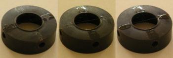
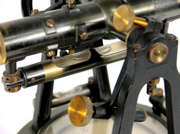
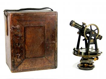
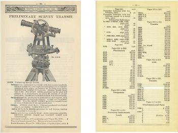
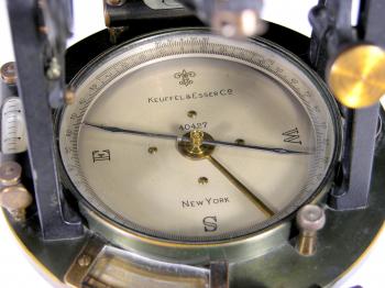
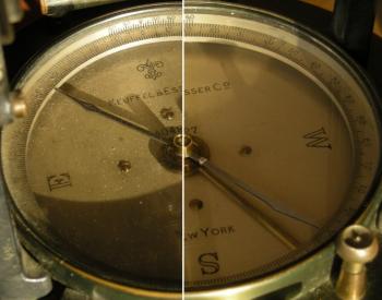
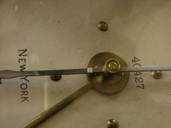
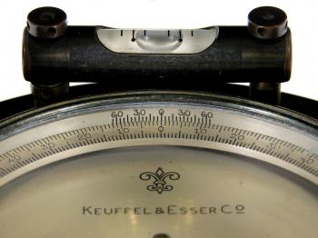
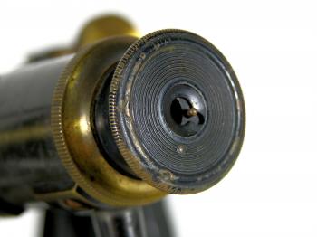
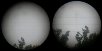
1919 Keuffel & Esser Preliminary Survey TransitI've obtained this Keuffel & Esser transit in 2008. Despite its age it is in remarkable good state. It still has most of its lacquered finish and a lovely patina at those places where it has gone. The instrument combines the functions of a theodolite with those of a compass. Basically it is a major improvement on the earlier graphometer. History The name 'Transit' finds its origin in the fact that the instrument was capable of vertically rotating (transiting) the telescope to show the observer the opposite direction of his last measurement. This was a great advantage in, for instance, rail road construction back in the 19th and early 20th century. In general transits were less accurate than theodolites, but the major advantage of the transit was that, while traversing using the compass, only half of the stations were required (see figure 26), although at the cost of some accuracy. Especially when setting out a route in unknown territory this method will speed up the whole process significantly. For this reason transits are still regularly used in pre-route surveys through dense forest or jungle where GPS fails due to poor reception. The method does however need a regular check of the magnetic deviation, which can be done by taking sun shots. The traditional transit as shown here was hugely improved by Heinrich Wild who, after creating his Wild T2 and Wild T3, created the Wild T0 in 1932. That transit has glass circles which are diametrically read by coincidence. The instrument is listed in the 1921 K&E Catalogue as 'Preliminary Survey Transit No. 5129N.'.1 According to the price list of that year (see figure 10) it would cost, including a box and tripod, US$205 (at that time approximately fl.695 or €315, roughly US$12,500.- or €9,100.- in 2009).2 This made it their cheapest transit with a compass and both horizontal and vertical limbs (model 5124 was without compass and vertical limb, model 5126 only had a vertical limb that would read down to 5 arc minutes). The diameters of the sexagesimal divided limbs are 5" (horizontal, 127mm) and 3½" (vertical, 89mm) and both can be read down to 1 arc minute. The compass has a 3½" needle and an adjustable limb, which allowed to correct for magnetic deviation (or otherwise to align the limb with the telescope). The base is quite different from modern theodolites. It has four adjustment screws and instead of being on top of a flat tripod table, it is screwed directly on the threaded head of a tripod (in this case 3" x 12). The 1921 catalogue tells us that '...four-screw instruments are the favorites of Engineers...', but that the tribrach types '...are beginning to find increasing favor in engineering circles, as [it] possesses many distinct advantages...', resulting in '...a higher degree of accuracy...'.3 Their high precision levels and theodolites were for this reason '...always furnished with three levelling screws...'.3 The base has a large hole by which the instrument can be centred above a geodetic marker. The instrument is finally fastened by turning the four adjustment screws until they get locked, in the meanwhile keeping the instrument's primary axis vertical. The '...8in, achromatic terrestrial...' telescope has an object glass of 1", a '...15 diameters...' magnifying power and fixed stadia hairs with a 1:100 ratio. The stadia hairs and reticle are made of cobweb. The spider silk would have been harvested from spiders collected by Mary Pfeiffer who was employed by K&E between 1889 and 1941 to run the spider ranch. She mainly used Epeira Diademata (also known as Araneus Diadematus or the Cross Orbweaver) and Zilla Atrica for the purpose.4 According to a Dutch book on surveying, the web of a Cross Orbweaver was also used for this purpose in the Netherlands.5 Of the four original hairs (one vertical and three horizontal), the vertical was missing when I obtained the instrument (see figure 3). I decided to restore the reticle for which the telescope had to be taken apart. First the eyepiece was removed (this can simply be screwed off), then the centring ring of it by loosening the four plain screws around it. The reticle is fastened with four capstan screws that allow to turn them using a pin. The reticle has that much play that it will simply roll out of the telescope once the screws are removed and thus care should be taken not to damage the remaining hairs. For the latter I used a socket wrench to support the reticle in the process (see figure 22). According to instrument manufacturer Gurley one can remove the diaphragm by taking out "... the side capstan screws from the cross-wire ring. With a sharpened stick, turn the cross-wire ring until in the same plane with the line of sight. Thread the stick into the hole in the cross-wire ring, unscrew the upper and lower capstan screws and draw it out".6 Up to here the process only took five minutes. The reticle was placed on a flat surface and cleaned from old lacquer where the vertical hair was once fixated. Then a fresh 30 centimetres long non-adhesive silk thread of a cobweb (a so called 'dragline silk': one of the threads the web was suspended with) was harvested in my garden, laid over the reticle while kept under tension and temporarily kept in place and under tension using two weights. Finally the thread was fixated with two small drops of colourless nail polish (see figure 4, nail polish has the advantage that it dries within several minutes, while a small soft brush comes with it). After re-assembling the telescope the instrument had to be aligned again. For this a target at about 150 metres distance was sighted in two faces, after which the instrument was set at the average angles. Using the adjustment screws the reticle was then moved back to the target. After that the instrument works fine, but the hairs are visually off-centred. In order to get them centred again, the eyepiece centring ring needs to be adjusted, which will only affect the field of view, not the calibration (see figure 24). In the meanwhile it was three hours later (the first attempt failed, the vertical hair broke while assembling, causing half an hour extra work). Limited by the resolution of the circles, but aided by a magnifying glass, I managed to calibrate the horizontal and vertical collimation to about 15-30 arc-seconds (7-14 centimetres at 100 metres distance) and the instrument is in working order again. Attached to the telescope is a large plate level (60 arc seconds per graduation, see figure 5) which allows it to be used as a levelling instrument. Although a case with plumb bob and oil bottle were supplied with the instrument (see figure 6), it is far from complete. The case lacks its floor board on which the instrument would be mounted before storing it inside. The floor board would have measured approximately 7" x 8½" x 7/8", with a 3" x 12 thread. In 2011 I finally found time to recreate the floor board, which I made of modern MDF and a bronze collar that I made on my lathe (see figure 8). The collar is fastened using three 1/4" bolts to the board. The instrument also lacks its lens cap (1 1/8"), sun shade, loupe, and adjustment tool(s) (I recreated the loupe and the pin that is used to adjust the vials etc.). Notes[1]: Catalogue of Keuffel & Esser Co., Manufacturers and Importers, Drawing Materials, Surveying Instruments, Measuring Tapes, 36th Edition, (New York, 1921), p. 321.[2]: Calculated using:
[4]: S.A. Bedini, 'Along Came A Spider - Spinning Silk for Cross-Hairs. The Search for Cross-Hairs for Scientific Instrumentation, Part II', in: The American Surveyor, Vol.2, No.3., (2005), p. 79. [5]: J.A. Muller, A. Scheffer, Landmeten en Waterpassen, (Haarlem, 1948), p. 44. [6]: W. & L.E. Gurley, Gurley Manual of Surveying Instruments (Troy 1941), p.38. If you have any questions and/or remarks please let me know. |
Surveyor's crosses... Geodetic Sextants... Theodolites... Total Stations... Levels... Standards... Tools... Firms...
19th c. SDL 1919 K&E 1926 Zeiss RThII 1924 Zeiss Th1 1929 Wild T2 1937 Wild T3 (astronomic) 1939 Wild T3 (geodetic) 1943 CT&S Tavistock 1948 Wild T1 1950s Askania Tu400 1952 Wild RDH 1956 Wild T0 1960s Zeiss BRT 006 1961 Wild T1A 1961 Wild MIL-ABLE T2 1962 Wild T2 1963 Wild RDS 1966 Kern DKM2 1969 Wild T2E 1969 Wild Di10 / 1972 T2 1976 Wild Di3S / 1963 T2 1976/79 Wild T2 mod - DI4 1990 Wild T2 mod - Di1000


