
Imaging Artefacts: Causes and Solutions1 April 2023 (© N. de Hilster & Starry-Night.nl) In astrophotography we do our best to produce the best possible picture of a piece of the sky. However, there are factors that can lead to artefacts in our recordings. But what exactly are artefacts, what is their cause and can they be prevented? This article, presented on April 1, 2023 during the spring meeting of the KNVWS workgroup Vereniging "Werkgroep Astrofotografie" (Association "Workgroup Astrophotography") in Gouda, delves deeper into the world of what we prefer not to see in our photos: artefacts. The artefacts are classified, explained and, if possible, solutions offered to prevent them.  Figure 1: Pillars of Creation in M16 showing diffraction spikes at all bright stars (Source: NASA). To begin with, I must first conceptualize the concept of artefact. In astrophotography, an artefact is a detail in the image that is not actually there in the sky and should therefore not be visible in the photo. Not all artefacts are undesirable or even preventable. Take the example in figure 1, a beautiful image of the Pillars of Creation, taken by the Hubble Space Telescope (HST). Although made with one of the world's best (and most expensive) telescopes under excellent conditions, since the HST is in space and therefore unaffected by the atmosphere, we clearly see artefacts around all bright stars: diffraction spikes. Now, these artefacts could easily have been avoided by opting for a different optical design. If a refractor or a Schmidt-Cassegrain design had been chosen instead of the current Cassegrain design, these artefacts would not have arisen. However, these other designs have practical drawbacks. For example, not only is it difficult to make a lens or corrector plate with a 2.4 metres diameter (the diameter of the main mirror of the HST), but also the weight and fragility played a role in the HST design. But where do these diffraction spikes and other artefacts come from? To this end, we can roughly classify them into five categories: 1) The Optical Tube Assembly (OTA)The vast majority of artefacts can be traced back to the OTA itself, whether caused by dirt or not, but that will be discussed later. Among the artefacts related to the OTA, we can distinguish between Intrinsic Artefacts (artefacts that belong to the OTA type) and Extrinsic Artefacts (artefacts that are caused by the OTA, but do not occur by default with this type of OTA). 1.1) Intrinsic OTA artifactsIntrinsic OTA artefacts are artefacts that we can expect from a particular type of telescope. In most cases they are accepted because they belong to the type of telescope, but in other cases they are perceived as disturbing. The (mostly) accepted artefacts are diffraction patterns inherent to the optical design. To understand them properly, we first need to see what exactly a telescope does to create artefacts. The light that enters a telescope inevitably encounters a number of obstacles. For example, in a refractor this is the edge of the objective, in a Schmidt-Cassegrain it is the edge of the aperture and the secondary mirror, and in a Newtonian telescope it is the edge of the aperture and the suspension of the secondary mirror (spider) and the secondary mirror itself. So there is not a single telescope where the light reaches the camera undisturbed. As soon as light passes an edge, diffraction occurs, which we see in the shape of the imaged stars.  Figure 2: The effect of the used optical design (left) on the diffraction (right). Figure 2 shows some examples of artefacts to expect at a given aperture (renderings made with ImageJ). It starts with a circular opening without any obstruction, but even then we see a diffraction pattern known as the Airy disc with diffraction rings. The next two are Newton-telescopes, the first with a classical quadruple straight spider, the second with a curved spider. It can clearly be seen that the first forms the known diffraction spikes (just like in the HST image), while these are absent in the second (but on the other hand, the light around the star is smeared, so the star becomes more diffuse). Next we see the diffraction pattern of a square, triangular and hexagonal aperture. As can be seen, there is little difference between the latter two, as both have only three main directions of edges (0°, -60° and +60° relative to the horizontal). The edges therefore only cause diffraction spikes in three directions at right angles to them. Now we won't use a square or triangular telescope anytime soon, but the sixfold mirror is well known with reflectors. The following plates show the sixfold opening in increasing honeycomb arrangement and finally also with three obstructions. The latter is exactly the design of the James Webb Space Telescope (JWST, the three obstructions are the suspension arms of the secondary mirror) and the last image in the animation shows an image from JWST with a bright star, showing exactly the predicted diffraction pattern. So it is clear that light passing through an edge causes a predictable diffraction pattern. The straighter the edge, the more striking the diffraction. We also know this effect from the Bahtinov mask. The pattern we use to focus is entirely caused by the straight slits in this mask. Once we start imaging, we remove the mask to prevent these diffraction patterns from being visible in the image. However, for the above diffraction patterns, we can only remove them by choosing a different type of telescope. There are also artefacts that are (usually) perceived as disturbing. These are artefacts that we do not expect with a certain type of telescope, but which nevertheless occur. The fact that they are mentioned here under the intrinsic artefacts is because all telescopes of this type (usually a certain model) show these artefacts. Dark spikes with varying orientation Figure 3: Rotating dark spikes in a Takahashi FSQ-85 (M42 Orion Nebula) image.  Symptom: Dark spikes with varying orientation can be recognized as a dark bar through the centre of the halo around bright stars. The orientation depends on the location in the image, as they are perpendicular to the direction to the centre of the shot. Symptom: Dark spikes with varying orientation can be recognized as a dark bar through the centre of the halo around bright stars. The orientation depends on the location in the image, as they are perpendicular to the direction to the centre of the shot.Cause: My suspicion is that this artefact is caused by an unfortunate lens spacing in combination with the type of coating of the lenses and that they are the result of physical amplification and extinction of the light. Solution: There is no known solution for this problem.  Figure 4: Rotating dark spikes in a William Optics GT102 refractor image (IC 2118 Witch Head Nebula). Examples: Figure 3 shows a Takahashi FSQ-85 image. The bright stars off centre all clearly show a dark spike perpendicular to the direction from the centre. A search on the Internet shows that almost all telescopes of this model show these dark spikes. That the Takahashi FSQ-85 is not the only telescope with this problem can be seen in Figure 4. The stars in this image of the Witch Head Nebula, taken with a William Optics GT102 refractor, show exactly the same pattern. However, with this telescope it seems to be exemplary, most pictures taken with other copies of this refractor do not show these artefacts. Comet-like stars Figure 5: Uncorrected f/3.9 Newton telescope versus Baader Rowe Coma Corrector.  Symptom: Stars off the centre of the frame take on the shape of comets, pointing towards the centre of the frame. Symptom: Stars off the centre of the frame take on the shape of comets, pointing towards the centre of the frame.Cause: This is coma, which is defined as a variation in magnification across the entrance pupil, and occurs mainly with reflectors with a parabolic mirror. Solution: Applying a coma corrector. Example: Figure 5 shows coma in an uncorrected f/3.9 Newton telescope and what it looks like after applying Baader Rowe Coma Corrector. H-alpha ghost-images Figure 6: Ghost images when using a tilt-tuned etalon.  Symptom: When recording with an H-alpha telescope (etalon), one or more ghost images of the Sun are visible in the background. Symptom: When recording with an H-alpha telescope (etalon), one or more ghost images of the Sun are visible in the background.Cause: The ghost images are the direct result of using a tilt-tuned etalon. Solution: There is no solution to this problem (other than using a pressure-tuned etalon). Example: Figure 6 shows ghost images of the Sun in an H-alpha image by Frank Theunissen with a tilt-tuned Lunt LS60THA. H-alpha Newton-rings Figure 7: Newton rings in an H-alpha animation.  Symptom: When using an H-alpha telescope (etalon), a pattern of light and dark curved bands is visible on the solar surface. Symptom: When using an H-alpha telescope (etalon), a pattern of light and dark curved bands is visible on the solar surface.Cause: The pattern are Newton rings due to the optical window of the camera sensor in combination with monochrome light of the etalon. An interference pattern is generated by the surfaces of the sensor and optical window as they interferometrically respond to the incoming monochromatic H-alpha light. In normal broadband light this would not be noticeable. Solution: There are two solutions: Tilting the camera or tilting the wavefront by means of an optical wedge (an ADC can be used for this). Example: Figure 7 shows Newtonian rings in an animation of the Sun in H-alpha, created by the author with a pressure-tuned Lunt LS80THA. In individual photos, the Newton rings are barely visible, but the animation makes them visible as a wave pattern moving from top right to bottom left across the image. H-alpha asymmetric illumination Figure 8: Setup with ADC behind a Lunt LS80THA.  Symptom: When imaging with an H-alpha telescope (etalon), the solar disk is not entirely evenly illuminated, which leads to a bright zone on the solar disk (dark in inverted processed). Symptom: When imaging with an H-alpha telescope (etalon), the solar disk is not entirely evenly illuminated, which leads to a bright zone on the solar disk (dark in inverted processed).Cause: These types of telescopes work with an etalon. Etalons have a zone of approximately one degree within which they work optimally, the so-called sweet-spot. When the centre of the sweet-spot is not aligned with the centre of the solar disk, it appears as an unevenly exposed image (in the left image, this is visible as a bright area at the top of the sun about 30% from the edge and with a diameter of about 50% of the solar disk). Solution: Centre the solar disk in the outgoing light beam of the etalon using an Atmospheric Dispersion Corrector (ADC), and centre it on the imaging chip. How to do this is explained in part 3 of my article on solar photography. Example: Figure 8 shows the imaging train with an ADC behind a Lunt LS80THA. 1.2) Extrinsic OTA artifactsExtrinsic OTA artefacts are artefacts that are caused by the telescope, but shouldn't be there. These are artefacts caused by incorrectly adjusted spiders, edge irregularities, pinched optics, reflections or incorrectly adjusted mirror spacing. In most cases they can be easily remedied. Double spider spikes Figure 9: Image of the area around Sadr with a SkyWatcher 150P Newton.  Symptom: Bright stars show split diffraction spikes. Symptom: Bright stars show split diffraction spikes.Cause: When the secondary mirror of a Newton, RC or Cassegrain is suspended with four vanes, these vanes are not neatly aligned two-by-two. This can happen if the secondary mirror mount is not properly centred in the tube or if the vane mounting holes are not neatly 'squared' in the telescope. Solution: There are two solutions: neatly centre the mirror or adjust the holes in the tube so that the vanes are again two-by-two in line (or at least two-by-two parallel to each other). Example: Figure 9 shows an image of the area around Sadr by Bill McSorley, Leeds, UK, taken with a SkyWatcher 150P Newton. Dark spikes with fixed orientation Figure 10: A small irregularity caused the dark-spike in the red-framed example.  Symptom: Bright stars show dark diffraction spikes with the same orientation all over the image. Symptom: Bright stars show dark diffraction spikes with the same orientation all over the image.Cause: The aperture has an unevenness. This could be a break in an O-ring on refractors or dirt or a protruding mirror clamp on reflectors. Solution: Determine where the unevenness is and remove it or stop down the aperture slightly. Example: Figure 10 shows the diaphragm ring of a Sharpstar SCA260 with a small obstruction (packaging material?) on it, which caused the dark spike in the image shown at the left (images by Maurice Toet). In later recordings this obstruction was gone and the dark spikes disappeared. Triangular stars (reflector) Figure 11: The Heart Nebula photographed with a Skywatcher 130PD with too tightly fastened mirror-clamps.  Symptom: Stars have a geometric shape (triangular, square) and look the same everywhere. Symptom: Stars have a geometric shape (triangular, square) and look the same everywhere.Cause: The mirror of the reflector is deformed by the tightly tightened mirror clamps (pinched optics). Solution: Loosen the mirror clamps slightly. Example: Figure 11 shows a crop of an image by kgunessee on Stargazer's Lounge of the Heart Nebula taken with a SkyWatcher 130PD with the primary mirror attached. Inquiries with the owner learned that after loosening the mirror clamps, this problem was solved. Pinched-optics (refractor) Figure 12: Stripped-down lens cell of a SkyWatcher Esprit triplet.  Symptom: Bright stars, especially in cold weather, have a halo with point-symmetrical dark spikes and look the same everywhere (left image by licho52 on Stargazer's lounge ). Symptom: Bright stars, especially in cold weather, have a halo with point-symmetrical dark spikes and look the same everywhere (left image by licho52 on Stargazer's lounge ).Cause: The lens (or lenses) of the refractor are distorted by overtightened centring screws. Solution: Loosen the centring screws evenly by a fraction (approximately 1/8 of a 360° turn, i.e. approx. 45°). NOTE: This is not without risk! With multiple lens groups (doublets, triplets) there is a risk that the lens group becomes out of collimation. Loosening the centring screws is best left to an expert. Example: Figure 12 shows a stripped-down lens cell of a SkyWatcher Esprit triplet clearly showing two rows of Allen centring screws and four rows of orange silicone fixing plugs (image by Teleskop Austria, Esprit tuning how we finetune Esprit80 and Esprit100). Pinched-optics (reflector) Figure 13: The set screws (B) of a standard RC8 (photo by Paul Volman).  Symptom: Bright stars have three dark and three light sections. Symptom: Bright stars have three dark and three light sections.Cause: The secondary mirror (in this case of an RC8) is distorted by overtightened collimation screws. Solution: With this type of telescope, the secondary mirror is completely glued to the aluminium plate on which it is mounted. When collimating, if the adjustment screws are overtightened, the secondary mirror will distort, resulting in this artefact. Example: Figure 13 shows a standard RC8 with the adjusting screws (B) visible and which were overtightened when the image in the red frame was taken. Asymmetrical halo Figure 14: Two images with a SW Esprit 80ED, left without diaphragm, right with.  Symptom: Halos around bright stars are not evenly bright all around (photos by the author with a SkyWatcher Esprit 80ED). Symptom: Halos around bright stars are not evenly bright all around (photos by the author with a SkyWatcher Esprit 80ED).Cause: Probably reflection along the inside of the lens cell or a coating that does not extend to the lens cell. Solution: Stop the aperture down by about 1 millimetre (make it smaller) with a very smooth diaphragm. Example: Figure 14 shows two images with a SkyWatcher Esprit 80ED, the left without, the right with a very smooth 79mm aperture aperture-disc. This makes the telescope f/5.06, which hardly affects the shutter speeds. Uneven halo Figure 15: Two images, at the left with a coarse diaphragm, on the right with a smooth one.  Symptom: Halos around bright stars have a halo (photos by the author with a SkyWatcher Esprit 80ED). Symptom: Halos around bright stars have a halo (photos by the author with a SkyWatcher Esprit 80ED).Cause: Uneven interior of the lens cell with refractors or diaphragm with reflectors. Solution: Make the lens cell or diaphragm smoother or stop down the aperture by about 1 millimetre (make it smaller) with a very smooth diaphragm. Example: Figure 15 shows two shots with a SkyWatcher Esprit 80ED, the left one with a paper aperture disc with an uneven edge, the right one with a very smooth 79mm aperture. This makes the telescope f/5.06, which hardly affects the exposure times. Ritchey-Chrétien (RC) Central Astigmatism Figure 16: Center crop of an RC16 shot with 25mm wrong mirror spacing.  Symptom: Stars are flattened (also in the centre of the frame) and their orientation rotates about 90 degrees when changing focus from inside-focus to outside-focus, giving the appearance of astigmatism (images by Robin David with an RC16). Symptom: Stars are flattened (also in the centre of the frame) and their orientation rotates about 90 degrees when changing focus from inside-focus to outside-focus, giving the appearance of astigmatism (images by Robin David with an RC16).Cause: This is most likely not a (significant) astigmatism of the main mirror, but an incorrect distance between the main mirror and the secondary mirror. Solution: Check the focal length by means of Ronchi-test or plate-solving and then adjust (+1mm change of the mirror distance gives an approximately -10mm change of the focal length). Example: Figure 16 shows a centre crop of an image taken by Robin David with an RC16 with 25mm incorrect mirror spacing (measured with plate-solving). After adjusting the mirror distance, the problem was solved. Truss-RC reflection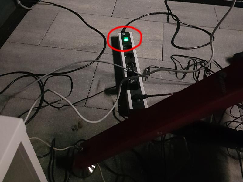 Figure 17: The reflection was caused by the light from a power strip switch.  Symptom: In the subs, taken with a truss-tube Ritchey-Chrétien telescope, a reflection resembling an out-of-focus donut is visible (photos by 'deepsky' with a 14″ truss-tube RC). Symptom: In the subs, taken with a truss-tube Ritchey-Chrétien telescope, a reflection resembling an out-of-focus donut is visible (photos by 'deepsky' with a 14″ truss-tube RC).Cause: Reflection in the secondary mirror from a light source in the background due to no light shroud being used. Solution: Prevent light from reaching the secondary mirror by means of a light shroud . Example: Figure 17 shows the power strip whose illuminated switch was the cause of the reflection. 2) Reducer, flattener in coma-correctorThe reducer, flattener, and coma corrector can also cause artefacts, both from pinched optics and incorrect distance from the camera. Pinched-optics (reducer/flattener) Figure 18: A William Optics Adjustable Flat6A III 0.8x Reducer/Flattener.  Symptom: Stars are not round and look the same everywhere. The artefact disappears when the reducer/flattener is removed (left photo by PirateMike on CloudyNights with an AstroTech (Telescope Service) 65EDQ). Symptom: Stars are not round and look the same everywhere. The artefact disappears when the reducer/flattener is removed (left photo by PirateMike on CloudyNights with an AstroTech (Telescope Service) 65EDQ).Cause: The pressure ring of the reducer/flattener lens group is too tight. Solution: Loosen the pressure ring slightly. Example: Figure 18 shows a William Optics Adjustable Flat6A III 0.8x Reducer / Flattener. The pressure ring is clearly visible here (inner ring on this side with two small holes). It can be unscrewed using a Lens Spanner Tool that grabs into the two holes. Incorrect back-focus Figure 19: Camera too close to the reducer/flattener (left), too far (right).  Symptom: Stars outside the centre of the image are stretched and all point toward the centre or in the direction perpendicular to it. Symptom: Stars outside the centre of the image are stretched and all point toward the centre or in the direction perpendicular to it.Cause: Wrong back-focus distance (distance between reducer/flattener and camera). Solution: Check back focus and adjust with shims. Example: Figure 19 shows that if the camera is too close to the reducer/flattener, the stars will point to the centre. If the distance is too great, they are stretched in the perpendicular direction (diagram by Helmut Eichler). 3) Filter artefactsFilter artefacts are artefacts that are purely caused by a filter. The problem then lies in the filter used, such as double reflections. Concentric reflections Figure 20: Image of the Pelican Nebula with clear concentric stars.  Symptom: Bright stars show multiple near-concentric reflections. In the centre of the image they are completely concentric, further out the double reflections shift outwards (i.e. away from the centre of the photo). Symptom: Bright stars show multiple near-concentric reflections. In the centre of the image they are completely concentric, further out the double reflections shift outwards (i.e. away from the centre of the photo).Cause: In this case it concerned double reflections within ZWO's old style H-alpha and S-ii filters. These filters were produced by ZWO until June 2018 and can be recognized by the white/yellow colour (front/back). After June 2018, ZWO improved the filters and they were recognizable by the white/purple colour. After mid-2020 they have been improved again, but unfortunately they have regained the old white/yellow colour, making them difficult to distinguish from the old style filters. See this post for tests with the first two types of filters. Solution: There is no solution for this (other than replacing the filters). Example: Figure 20 shows an image of the Pelican Nebula with clear concentric halos around the brightest stars. After replacement with new style ZWO filters this artefact disappeared. Concentric flats artifacts Figure 21: ZWO EFW filter wheel with one of the filters fitted with a filter mask.  Symptom: Flats exhibit concentric circular artefacts. Symptom: Flats exhibit concentric circular artefacts.Cause: Light leakage along the edges of unmounted filters. Solution: ZWO has special masks for their unmounted filters that cover the edges and with which these artefacts disappear completely. Example: Figure 21 shows a ZWO EFW filter wheel with one filter fitted with a filter mask (the rest followed later). 4) Camera artefactsCamera artefacts are artefacts that are purely caused by the camera. So in most cases the problem is in the camera, such as tilt of the sensor, micro-lensing and varying Gain and Offset of the photosites. Sensor tilt Figure 22: One of the ways to check sensor tilt with a laser.  Symptom: Stars are increasingly stretched in one direction. Symptom: Stars are increasingly stretched in one direction.Cause: The camera is not perpendicular to the telescope, caused by tilt in the attachment of the focuser to the telescope or of the camera to the focuser, in many cases caused by the fact that the camera is not screwed, but attached to the focuser with a clamp connection. Solution: Fix the camera with a screwed connection or use a tilt adapter and correct it. Example: Figure 22 shows one way to check and possibly adjust the tilt of the camera sensor with a laser (see Andrew Burwell's description). With this method, the camera is mounted on a 2″ bearing block, but there are cheaper solutions where the camera only rests on a shelf (directly below the video). Alternatively, the tilt can be remedied using a Bahtinov mask (i.e. without a laser). Micro-lensing Figure 23: Cross-section of an imaging chip (left), mathematical reconstruction (right).  Symptom: Bright stars have eight distinct reflections (or a multiple of them) that sometimes merge into a bright square around the star. Symptom: Bright stars have eight distinct reflections (or a multiple of them) that sometimes merge into a bright square around the star.Cause: The photo was taken with a camera equipped with micro-lenses, such as the ZWO ASI1600MM or QHYCCD QHY163. These micro-lenses provide extra light throughput to the photosites (pixels), but also give reflections towards the sensor window. It are these reflections that provide the artefact. Solution: There is no solution (yet) for this artefact (other than using a different type of camera). Perhaps this can be solved with software. Example: Figure 23 shows a cross-section of an imaging chip with a photo-site with micro-lens on the left and without a micro-lens on the right (source: M. Abramowitz, MW Davidson, Concepts in Digital Imaging Technology: Microlens Arrays). The image on the right shows a mathematical reconstruction of the artefact by Mark 'sharkmelley', so perhaps one day there will be a software solution for suppressing it. Monochrome Bayer pattern Figure 24: Sun in H-alpha with a QHY163 mono, stacked on the left without blur, on the right with 1.5px blur.  Symptom: Monochrome images show a chequerboard pattern (particularly visible in lucky images of the Sun in white light and H-alpha). Symptom: Monochrome images show a chequerboard pattern (particularly visible in lucky images of the Sun in white light and H-alpha).Cause: According to Qiu Hongyun, the founder and CEO of QHYCCD, this is caused by the photo being taken with a camera equipped with an image chip originally developed for an OSC camera (in this example a Panasonic MN34230ALJ Maicovicon® sensor that is used in the ZWO ASI1600MM and QHYCCD QHY163 mono). The photo sites on this image chip are already prepared for use with a Bayer colour filter layer and therefore have slightly different Offset and/or Gain settings per RGB photo site. Solution: In AutoStakkert! can be solved by applying a pixel and a half blur when stacking (via experimental settings). Since the blur is applied prior to stacking, the level of detail is not compromised. Remaining artefacts can be removed by applying a 0.55px Gaussian blur afterwards. Example: Figure 24 shows an image of the Sun in H-alpha with a Lunt LS80THA refractor and QHY163 mono camera (images by the author). The recording is done twice with AutoStakkert! processed: left stacking without blur, right with 1.5px blur. Ice formation Figure 25: Image of M63 with branch-like ice formation along the edges (photo by Paul Volman).  Symptom: Subs show strange spots in the centre or dark branches (dendrites) along the edges. Symptom: Subs show strange spots in the centre or dark branches (dendrites) along the edges.Cause: Ice formation that occurs with cooled cameras. Solution: There are two types of cooled cameras: those that are kept dry with desiccant tablets and those that are filled with a rare gas (Argon, etc.). The desiccant tablets can be dried in an oven or microwave. The gas-filled cameras eventually lose their gas filling, after which refilling is necessary. Example: Figure 25 shows an image of M63 with branch-shaped ice crystals along the edges. 5) DirtDirt in the optical train, especially in the first centimetres from the imaging chip, can cause so-called Dust bunnies. Dust-bunnies Figure 26: Calculating the distance to the dust that causes the dust bunny.  Symptom: Doughnut-shaped dark areas of different sizes in the astro-images. Symptom: Doughnut-shaped dark areas of different sizes in the astro-images.Cause: The majority of conspicuous dust bunnies are caused by dust particles in only two locations: the sensor window and camera window. Depending on the distance to the image chip, dirt on the filters can also cause clear dust-bunnies, but in general, dirt on surfaces that are more than a few centimetres from the image chip no longer cause clearly visible dust-bunnies. Solution: There are two solutions: Taking flats and applying them in the processing, or cleaning the camera properly (a combination is of course also possible). Example: Figure 26 shows a flat frame made with a SkyWatcher Esprit 150ED refractor and ZWO ASI1600MM Pro Cool monochrome camera. Three sizes of dust bunnies are visible. The smallest are caused by dust particles that are directly on the sensor window (that is the glass plate that is attached to the image chip), the next size is on the inside of the camera window (the glass plate that is in the camera housing), the largest are caused by dust on the outside of the camera window. The distance from the image chip where the dust is located can be calculated from the diameter of the dust-bunny in pixels multiplied by the pixel size and by the focal-ratio (the outcome is in the same units as the pixel size). The table in figure 26 shows this for the f/7 Esprit 150ED and a camera pixel-size of 3.8 microns. Obviously, the distance is affected by the refraction of light through the glass windows. If its thickness and composition is known, then a correction for the distance can be calculated. In the case of the ASI1600, the camera window is made of BK7 glass with a thickness of 2mm, the correction for this is then 0.34 x 2 = 0.68mm (the dust seems to be closer than it actually is). The thickness of the protect-window on the image chip is unknown, but if we assume 1mm, then a correction of 0.34mm follows. The outer dust particles are therefore at least 4.4+0.3+0.7 = 5.4mm from the image chip (the calculation is not 100% conclusive: the camera window would be 2mm thick, but from the calculation follows 1.5mm). Dirty corrector plate Figure 27: Full view of a bright star with a dirty Intes MK-72 Maksutov (photo by Paul Volman). 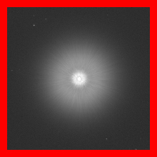 Symptom: Bright stars in subs taken with a Maksutov telescope have a large halo. Symptom: Bright stars in subs taken with a Maksutov telescope have a large halo.Cause: Dirt on the corrector plate. Solution: Clean the corrector plate (this video shows how to do this with an SCT, but the method can also be used on a Maksutov). Example: Figure 27 shows the full image of a bright star with a dirty Intes MK-72 Maksutov. 6) External factorsArtefacts are not always caused by the telescope and optical train. Sometimes external factors such as obstructions above the setup or the observatory itself play a role in causing artefacts. Rotating diffraction-spike Figure 28: Roterende diffraction-spike  Symptom: Diffraction spike that twists with time (the left picture was taken by Arie Bakx with a 10″ newton in a 2 meter diameter ScopeDome). Symptom: Diffraction spike that twists with time (the left picture was taken by Arie Bakx with a 10″ newton in a 2 meter diameter ScopeDome).Cause: The telescope is partly looking at the edge of the slit in the dome during imaging. Since this edge is almost straight, a diffraction pattern will be formed perpendicular to that edge. Solution: Re-synchronize the dome. Note that not all imaging software can properly handle a side-by-side setup. If there is no setting in the software for the lateral offset, this can cause the telescope to image along the edge of the slit. Example: Figure 28 shows the dome that caused the spinning diffraction spike in the accompanying animation (image by Arie Bakx). Combined light and dark diffraction spike Figure 29: A typical case of a location where we can expect diffraction spikes. 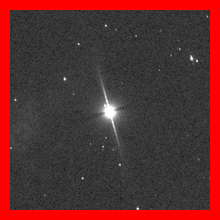 Symptom: Combination of a light diffraction spike with a dark one perpendicular to it. The artefact is uniform throughout (the left image was taken by Malcolm M with a Takahashi FS60CB ). Symptom: Combination of a light diffraction spike with a dark one perpendicular to it. The artefact is uniform throughout (the left image was taken by Malcolm M with a Takahashi FS60CB ).Cause: The telescope looks through overhanging cables (high voltage, telephone) during imaging. Since these cables are almost straight, there will be a light diffraction spike here that is perpendicular to that cable and a dark one parallel to it. Solution: Move the imaging setup. Example: Figure 29 shows a typical case of a location where we can expect diffraction spikes (source: Pole of the Month September 2022). Dark border in planetary images Figure 30: Two images of Mars taken on December 26, 2022, but with two different cameras.  Symptom: In planetary images, a dark shadow is visible along (part of) the edge. Symptom: In planetary images, a dark shadow is visible along (part of) the edge.Cause: Martin R Lewis describes on his website that there is no clear explanation for this phenomenon, known as the edge-rint effect. Some cameras seem to be more affected by this phenomenon, as are some telescopes, but at the same time the seeing also seems to play an important role. Solution: Experiment with other camera(s) and conditions to find the optimal situation for the set-up used. In addition, an apodising mask could have a beneficial effect, but more research is required. Sharpening the data while the planet is pasted on a lighter background also helps prevent the edge-rint effect. Example: Figure 30 shows two images of Mars taken on the same night by the author, but with two different cameras. Although no edge-ring is generally visible with the ASI174MM, it also occurs sometimes with that camera. If you have any questions and/or remarks please let me know. |
InFINNity Deck... Astrophotography... Astro-Software... Astro Reach-out... Equipment... White papers...
Hardware... Imaging...
Imaging artefacts Optimal focal ratio (part 1) Optimal focal ratio (part 2) Solar imaging (part 1) Solar imaging (part 2) Solar imaging (part 3)