
1980 SAT AGA-Minilir Figure 1: The 1980 SAT/SAGEM AGA-Minilir. The instrument shown here is one of legendary proportions here in the Netherlands and was donated to my collection in 2012. The basis of the instrument shown here is the French Minilir, which was the product of an internal research project of SAT (Société Anonyme de Télécommunications) and first created in 1972.1 The instrument is based on a 1953 patent and many others of the years following up to 1970s. The Minilir was not purely geodetic development but a military one for automatic tracking of infra-red sources, such as missile exhausts. It was used as a missile tracking system on firing ranges Centre dEssais des Landes2 and Hammaguir3. In combination with a film camera the system became known as a cinéthéodolite, which have been used on launch sites Kourou (Guiana Space Centre) and Cape Canaveral. In civil use the Minilir has been used for calibration of ILS (Instrument Landing Systems).2 When the instrument arrived in the collection it came with an IBEO Fennel electronic distance meter (EDM). Originally the first Minilir, the one shown here, was bought with a AGA Geodimeter 112 EDM, and so were the others that followed. These AGAs had however been replaced with the IBEO Fennels, as they had been worn out after years of continual use on the Eastern Scheldt Storm Surge Barrier (see below), and were simply discarded. In 2015 I managed to track down an AGA 112 that was only a few serial numbers off the AGA 112 that had been originally bought for the first Minilir. Depending on which EDM was in place the instrument as a whole was referred to as AGA-Minilir (see figure 1) or Fennel-Minilir (see figure 3).  Figure 2: The SAT autopointeur, the direct predecessor of the Minilir. Development The Minilir was a product of a long term development within SAT that started with the take-over of the workshops of Jean Turck in 1956. This company was active in the field of infra-red sensing and defence systems. Four years later they started researching the feasibility of infra-red seekers for missiles (i.e. integrated systems in the missile to steer it towards its infra-red target). After having developed several of these systems, such as the R530 and R550 (also known as MAGIC 1) that were based on single cell detectors, SAT started developing matrix based detectors, the first of which were built in 1971. On the path towards this development SAT also developed their first infra-red guidance system, the Autopointeur pour caméra cinématographique (auto pointer for film cameras, see figure 2). It was used somewhere before 1967 at Colomb Béchar, the first French firing range in Algeria, to follow and film projectiles. This autopointeur was the predecessor of the Minilir that was used on the later Algerian firing range Hammaguir.  Figure 3: Fennel-Minilir with telemetry and remote control. Introduction into the Netherlands Developed in 1972 the Minilir became known in the Netherlands around 1976 thanks to Hans van der Wal, the Francophile head of the Marine Geodesy department of the Dutch Governmental Survey Department (Meetkundige Dienst, afdeling GAM or MD/GAM in short). Married to a Frenchwoman Van der Wal moved in French circles and became well known with French instruments which he subsequently introduced to the Survey Department.4 In 1976 initial tests were done with a Minilir that was provided by the manufacturer for the purpose. Most of the tests were conducted on board of a vessel and were to see what the effects were of line of sight interruption and to track down possible error sources. Also the optimum infra-red source (a single 100 or 150 watt halogen light bulb) was researched (figure 28 shows the prototype target with three light bulbs). After these initial tests research was continued using two Minilirs, which both were using the same infra-red target on board of a vessel. The data from the first Minilir was sent by telemetry to the location of the other where both signals were combined using a HP9835 computer. Purpose of this test was to see how well the system performed in vertical direction and to test the telemetry. As a result of these tests the Minilir was later used to test hydrographic motion sensors.4 The potential of the Minilir's autotracking capabilities was recognized with the following possible applications:5
 Figure 4: The AGA-Minilir during the construction of the Eastern Scheldt Storm Surge Barrier. EDM The instrument was combined with an Electronic Distance Meter (EDM, see figure 4) and accurate Wild Heerbrugg GFL 1 coincidence vials (see figure 25). In this set-up the instrument became the very first autotracking total station. During the first ten years the AGA 112 was used as EDM (see figure 15 and figure 17), which however - due to internal calibrations - stopped providing data every 42 seconds for 3 seconds. As the AGA-Minilir was intended for dynamic positioning this gap in the data stream was undesirable. In order to overcome this - and as the original AGA's were coming to the end of their useful lifespan - tests were done in 1991 with the Ibeo Fennel PS 50 (see figure 16 and figure 18) to replace the AGA 112. The first Fennel-Minilir combination became available per August that year. The results were that successful that it was advised to replace the AGA's of the other two Minilirs as well.6 Sadly enough the original AGAs were discarded in 1998.7 Depending on which EDM was in place the instrument as a whole was referred to as AGA-Minilir (see figure 1) or Fennel-Minilir (see figure 3). The Eastern Scheldt Storm Surge Barrier Figure 5: The construction of the Eastern Scheldt Storm Surge Barrier. On 1 February 1953 a storm surge caused a catastrophic disaster at the south-east coast of England, the coast of Belgium and the south-western coast of the Netherlands. Here in the Netherlands an area of 150,000 hectares (370,000 acres) was flooded, taking the lives of over 1,800 people. A further 70,000 people had to be evacuated, while the damage to property amounted to 1,500 million guilders.8 Three weeks after the disaster the Delta Commission was set up in order to device a plan to tackle the problems in the Delta region. The plan consisted of closing all tidal inlets, except the New Waterway and the Western Scheldt, and raising and strengthening the dikes along the remaining tidal waters. In 1973 a committee was asked to investigate the option to leave the Eastern Scheldt open for sake of the environment. At the end of 1974 it was decided to create a storm surge caisson dam, the plans of which - estimated at 4,265 million guilders - were published in 1976. The idea consisted of creating a barrier that could be closed in about 1 hour, whether the tide was running or not.8 The plan consisted of three individual barriers with a total of 66 piers with a maximum weight of 18,000 tonnes each (footprint 25 x 50 metres, maximum height 40 metres). The piers were spaced 45 metres apart and had to be placed with a tolerance of only 30 centimetres in X and Y direction (the Z was controlled by the seabed which was cleaned, compacted and levelled within a 25 centimetres tolerance) and a rotational tolerance along the Z-axis of 7 millimetres per meter.9 As GPS was still in its infancy no accurate real time alternative 3D positioning system - apart from the Minilir - existed to fulfil these requirements. The Minilir was initially used to position the Mytilus that compacted the seabed. The second vessel using the Minilir was the Cardium during the deployment of the foundation mattresses for the piers. Finally the combined data of three Minilirs was used to position the piers of the barrier using the vessels Macoma and Ostrea (see adjacent picture). Later the sill beams between the piers were placed by the Taklift 4 crane pontoon using Minilir for positioning.4,5  Figure 6: Krupp Atlas Polartrack (left) being tested against the Fennel-Minilir. Provenance In 1980 the instrument was - together with another two and several other geodetic instruments like the 1980 Wild TC1 in my collection - purchased for the construction of the Delta Works, while an additional three Minilir's were hired from the manufacturer. They were used by the surveyors that worked for DOSbouw After the Delta Works the three hired Minilirs returned to SAT, while the other three passed on to MD/GAM. They have been used in a variety of applications since, mainly to check other positioning systems like the Krupp Atlas Polartrack (see adjacent picture) and various GPS systems. In 1997 the instruments were handed over to DCI Electronics, the firm that maintained and stored the instruments for MD/GAM since they were used at the Delta Works.10 A new telemetry set was ordered and delivered for the system, but the system would never be used again.11 One of the Minilirs was eventually sold to an Italian firm, of the second the current location is unknown, while the third remained in their possession.11  Figure 7: The AGA-Minilir and Leica TCRA1101 side by side. In the meanwhile technology had advanced and lighter total stations, like the 1999 Leica TCRA 1101 (see adjacent picture), with better capabilities for a fraction of the price (and weight!) of a Minilir became available. These were however not yet capable of providing the same accuracy at larger distances under dynamic conditions.4 It was the advent of RTK-dGPS receivers that rendered the Minilir old fashioned as soon as it had proven their accuracy. The accompanying Ibeo Fennel PS 50 of the last remaining Minilir at DCI had been given to a former colleague, while the Minilir itself rested on a shelf. It was in 2012 that I contacted DCI in the hope they still owned one and wanted to part from it. On condition that I would take proper care and to never dispose of it I was allowed to collect it.12 Luckily my former colleague still had the Fennel which he gladly donated to reunite it with the instrument. A few years later, in 2015, I managed to track down an early AGA Geodimeter 112. Its serial number 23093 was very close to that of the first acquired AGA 112, which had serial number 23032,13 and showed the same design as the original one. Over time two different versions of the AGA 112 have been used with the Minilir, only discernible by their design (see figure 12 where a former colleague can be seen between two Minilirs with the two versions of the AGA 112). The original AGAs had their carrying handles replaced by telescopic rifle sights. When the AGAs were discarded a former colleague took one of the sights off and kept it at home as a souvenir. Now, 17 years later, it has been donated to the collection as well to be mounted on top of the newly acquired AGA 112 (see figure 11).  Figure 8: The complete Minilir set, here with the Fennel EDM mounted. Accuracy Accuracy-wise the Minilir is similar to the Wild TC1 that served as a back-up system. Both the vertical and the horizontal circle have an accuracy of 4.5 arcseconds or just over 0.001 degrees (2-3 arc seconds for the TC1). The Wild Heerbrugg GFL 1 vials have an accuracy of 160 arcsecond/2mm that - thanks to the coincidence method - allowed the Minilir to be levelled with an accuracy of 1.5 arcseconds. The Fennel has a dynamic precision of 10mm (5mm for the TC1 under static conditions).14 The update rate of the Minilir is 5Hz, where the vertical and horizontal angles were supplied in turns every 0.1 second. The AGA 112 was used in tracking mode which gave it an accuracy of 20mm + 5ppm.15 The Fennel was used with an update rate of either 7.1Hz or 3.6Hz in which it had an accuracy of respectively 10mm and 5mm.16 When I used the Fennel-Minilir combination myself at the Ketelmeer in 1996, the average lateral error on 14 orientations (static measurements) at 883 metres distance was 0.007m with a standard deviation of 0.010m (1σ, 68%), while the vertical error was 0.014m with a standard deviation of 0.006m (1σ, 68%).17 The error in distance measurement was -0.010m with a standard deviation of 0.000m (1σ, 68%).18 Dynamically the piers of the Eastern Scheldt Storm Surge Barrier could be positioned at 800 metres distance with an accuracy of approximately 0.020m in X/Y and 0.023m in Z (1σ, 68%).19 The accuracy literally came at a heavy price: The Minilir alone - without its tribrach (see figure 27), tripod and flight case (see figure 9) - weighs 38 kilograms, which is almost four times as much as the Kern E1 and Wild TC1 in my collection. It comes with four external units for analysing the IR signal, creating the digital output and for transmitting and receiving the data by telemetry. In addition to that a remote control was available. Together with the tripod and tribrach the whole system weighs some 200 kilograms and needs a small van for transportation. Relying on 220 volts power supply a generator was often used to get the system running. Money-wise the Minilir would easily have bought ten of the best period total stations. Notes[1]: SAT web site Histoire Générale.[2]: SAT web site article. [3]: Dugarre, C., 'Missiles and Spaceflight... Sahara Test Centre', In: Flight, 13 February 1959, p.213. [4]: From correspondence with A.P.M. Pieters, former employee of the Survey Department and involved in the initial tests with the Minilir and the surveys of the storm surge barrier. [5]: Rijkswaterstaat, 'Een halve Eeuw Meetkundige Dienst, 1931 - 1981', in: Publicatie van de Rijkswaterstaat Meetkundige Dienst te Delft, 35 (oktober, 1981), (Delft, 1981), pp.87-88. [6]: Internal Rijkswaterstaat e-mail 'testen Fennel 50 afstandsmeter tbv vervanging AGA 112.', 23 April 1992. [7]: Internal Rijkswaterstaat document A.P.M. Pieters, Inventarislijst Ad Pieters, juli 1998, (Delft, 1998). The inventory list reads "afgevoerd naar Roteb zie lijst" (conveyed to Roteb, see list). [8]: W. Colenbrander (ed.), Rijkswaterstaat Dosbouw, Eastern Scheldt Storm Surge Barrier, (1980), pp.4-7. [9]: Magazine Cement, Eastern Scheldt Storm Surge Barrier, Proceedings of the Delta Barrier Symposium, Rotterdam, 13-15 October 1982, (Waalwijk, 1982), pp.89-90. [10]: Internal Rijkswaterstaat document: A.P.M. Pieters, 'Bedrijfseconomische raming t.b.v. contract DCI, 1 jan '96 - 31 dec '96.', (Delft, November 1995). [11]: With many thanks to director of DCI, A. Hoogesteger, for these details. [12]: N. de Hilster, A.P.M. Pieters 'AGA/Minilir, de Eerste Zelfvolgende Tachymeter', in: De Hollandse Cirkel, Jaargang 14, nr. 4, (2012), pp.141-147. [13]: Internal Rijkswaterstaat document: Inventarislijst Meetkundige Dienst, Afd. GAM: Materiaal verhuist [sic.] van DCI naar Delft, februari 1996, (Delft, 1996). [14]: Internal Rijkswaterstaat document: A.P.M. Pieters, Nauwkeurigheid Minilir, (Delft, 1995). [15]: AGA, Geodimeter 112: Technical Specification, (1980). [16]: Internal Rijkswaterstaat document A.P.M. Pieters, Minilir / Pulsar 50: Offset's, instellingen enz. behorende bij de MINILIR / PULSAR 50 combinatie., (Delft, 1996). [17]: A.P.M. Pieters, N. de Hilster, Baggerproef 4 Ketelmeer, Verslag 1e lijnsverwerking meetnauwkeurigheid, (Delft, 1996), p15. [18]: ibid. It has to be noted that the distance measurement was done in centimetres. [19]: J. van den Berg, Nauwkeurigheidsbeschouwing Ostrea, (1982), pp. 28-31. Picture reference Apart from the following list, all pictures by N. de Hilster: Fig. 2: Classements des photos page of the SAT Souvenir web site. Fig. 4, 6, 24, 25, 26, 28, 29: Collection A.P.M. Pieters. Fig. 5, 27: Hoofddirectie van de Rijkswaterstaat, Bureau Reprografie (pictures 23/09/1983:175 and 05/02/1985:49). If you have any questions and/or remarks please let me know. |
 Figure 9: The instrument and its case, tripod and tribrach. |
 Figure 10: A close-up of the reflecting telescope. |
 Figure 11: The early type AGA Geodimeter 112 as was originally bought with the Minilir. |
 Figure 12: Former coleague Bart Valstar with two AGA-Minilirs, the one at the right with the old model AGA 112. |
 Figure 13: The 'Coffret IR' that controls the IR detection. |
 Figure 14: The 'Coffret Codage' for digitizing the circle readings. |
 Figure 15: The AGA Geodimeter 112 mounted on the Minilir. |
 Figure 16: The AGA 112 was replaced by the Ibeo Fennel PS 50 in 1991. |
 Figure 17: The AGA Geodimeter 112 from the other side. |
 Figure 18: The AGA 112 replaced by the Fennel PS 50. |
 Figure 19: The telescope is ballasted to counterweight the EDM. |
 Figure 20: The Minilir was last serviced on 4 December 1997. |
 Figure 21: Several labels are attached to the Minilir. |
 Figure 22: A joystick allows to take over control over the instrument. |
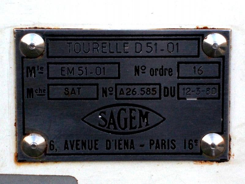 Figure 23: Close-up of the SAGEM label showing contract number 16 and order date 12/03/1980. |
 Figure 24: Close-up of the SAT label showing the instrument's name Minilir and serial number 17. |
 Figure 25: The Minilir is equipped with two Wild GFL 1 coincidence vials. |
 Figure 26: The tribrach is mounted using three standard Wild screws. |
 Figure 27: The tribrach compared to a Leica tribrach. |
 Figure 28: The prototype target. |
 Figure 29: Ko Dekker and Jan Hoogstad at the Delta Works (September 1983). |
 Figure 30: A peek into a similar survey cabin on the Delta Works (1983-1984). |
 Figure 31: Lou de Jonge at the Delta Works with Minilir and Wild TC1 (1982). |
 Figure 32: Yet another survey cabin on the Delta Works with two AGA/Minilirs (05/02/1985). |
 Figure 33: The arrows indicate the positions of three of the Minilirs (September 1983). |
 Figure 34: Survey cabins with three AGA/Minilirs. |
Surveyor's crosses... Geodetic Sextants... Theodolites... Total Stations... Levels... Standards... Tools... Firms...
1970s HP 3810A 1980 SAT AGA-Minilir 1980 Wild TC1 1980s Zeiss Elta 20 1984 Kern E1 1986 Geodimeter System 400 1992 Krupp Atlas PolarTrack 1999 Leica TCRA 1101